Context
For our UCSB Computer Engineering capstone, Scopen was not intended to replace a laboratory oscilloscope. We focused on the essential path: condition the input, sample it reliably, move the data wirelessly, and present it clearly on a desktop.
The rest of the project follows that signal path from the circuit board to firmware, software, and the enclosure.
Hardware
Two systems, one very narrow board.
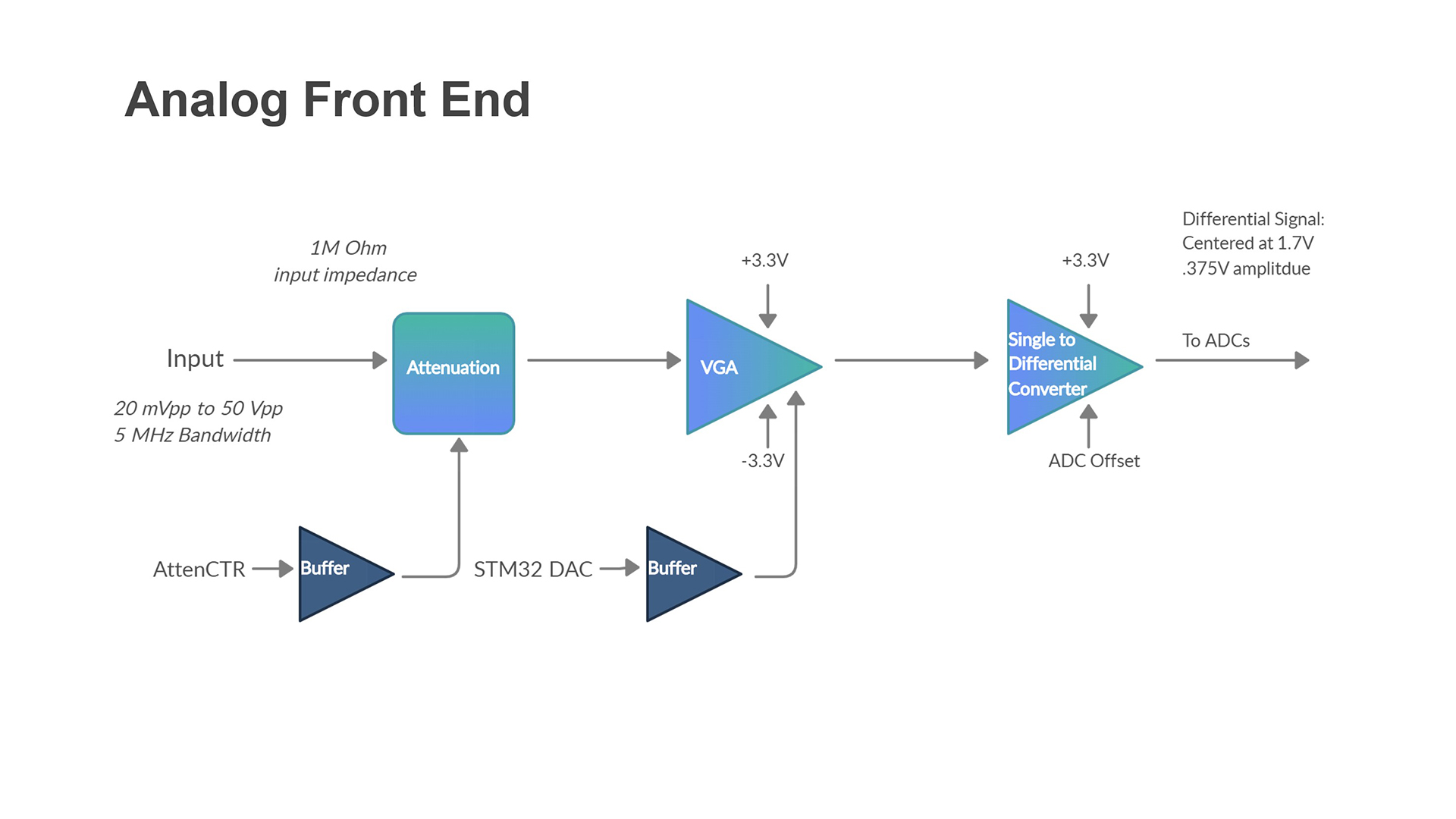
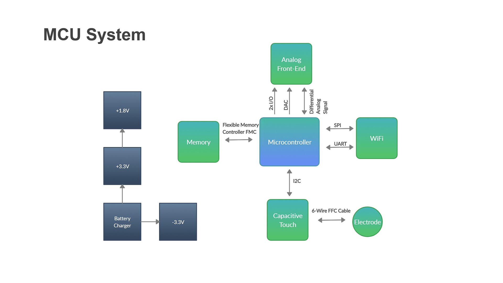
The board combines an isolated analog front end with an STM32 and ESP32 control system. One path conditions the signal; the other samples, stores, and transmits it.
That packaging constraint shaped the board before it shaped the enclosure. Components occupy both faces of the same narrow footprint.
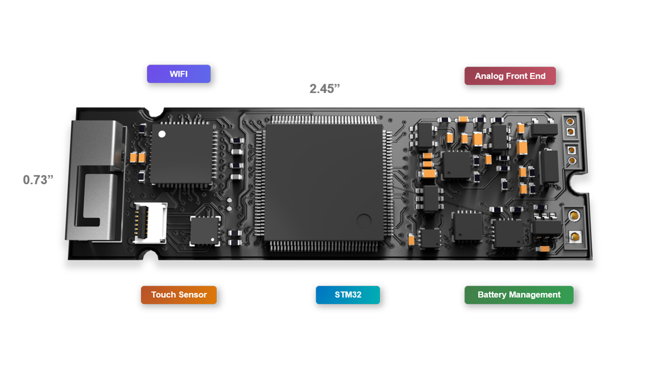
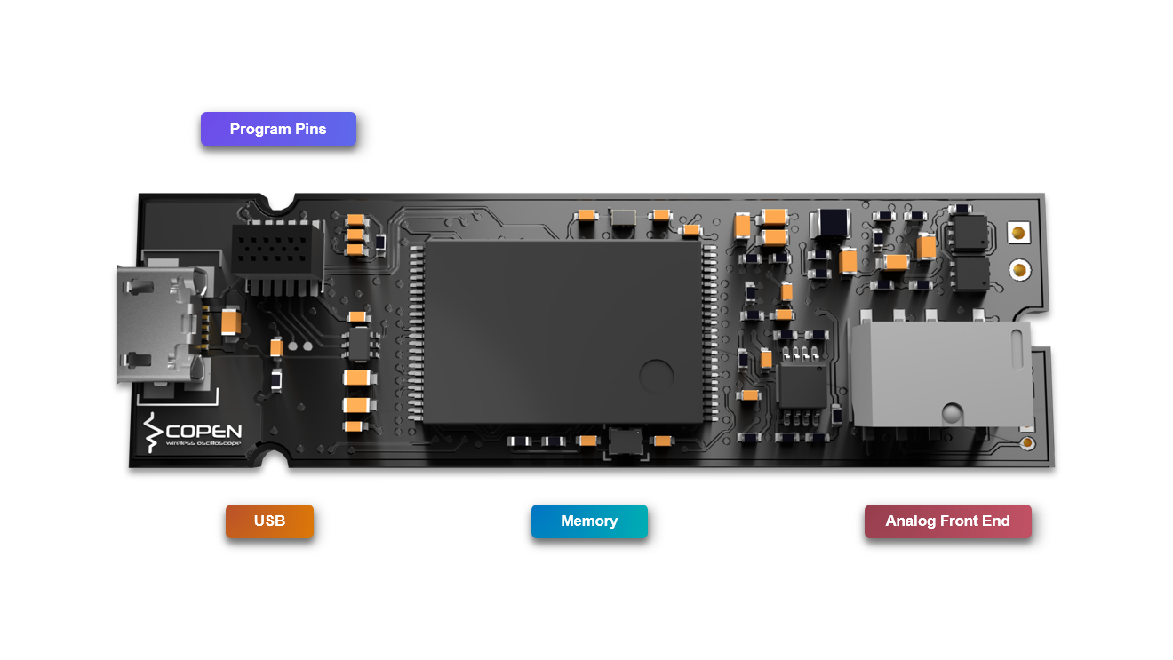
The two populated faces solved the component-density problem. The six-layer stack handled routing, power distribution, and separation between the signal and control domains.
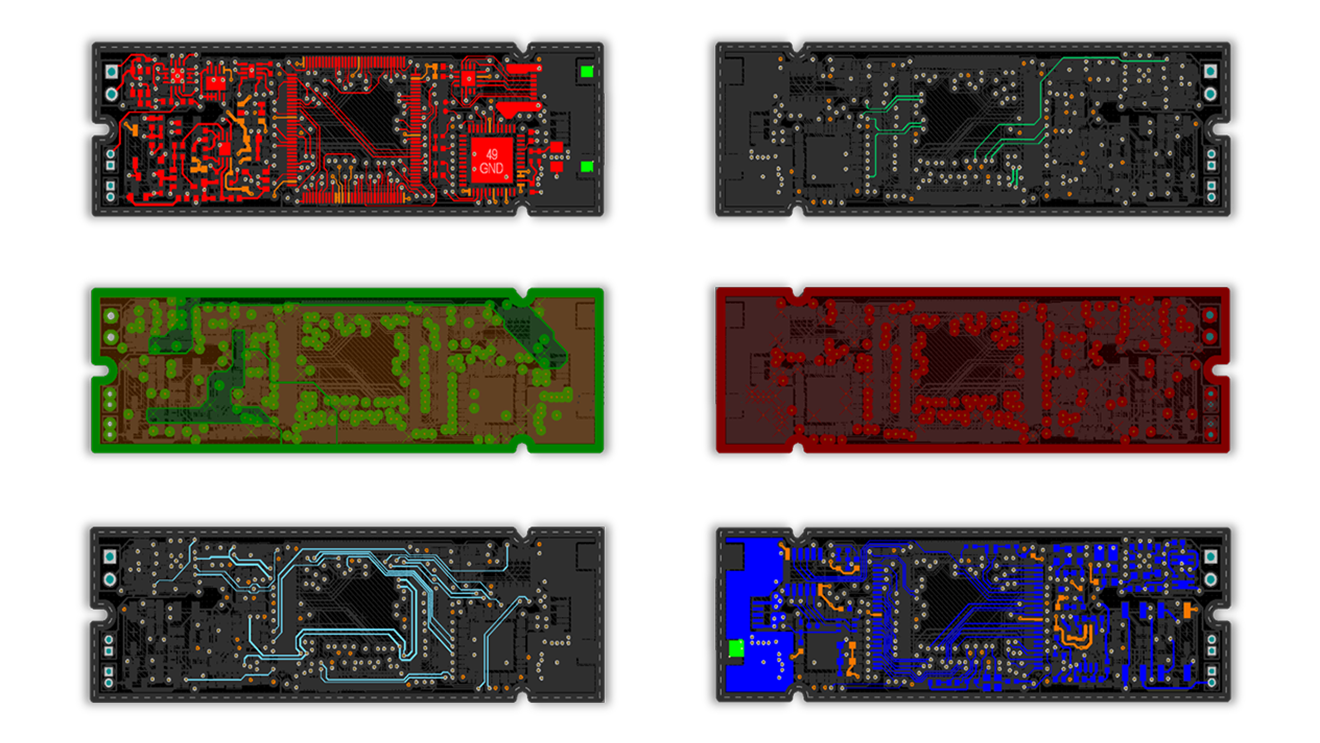
The physical stack supports two electrical domains that must cooperate without compromising the signal. The analog path conditions the input; the controller path captures the result and coordinates every other subsystem.
Firmware
Keep sampling deterministic. Move everything else around it.
The firmware spans two controllers. An STM32 handles acquisition, local storage, touch input, and device state. An ESP32 bridges the instrument to the desktop application over WiFi. The system is divided by responsibility rather than by feature: time-critical acquisition stays close to the STM32 peripherals, while communication and product behavior run in layers above the hardware drivers.
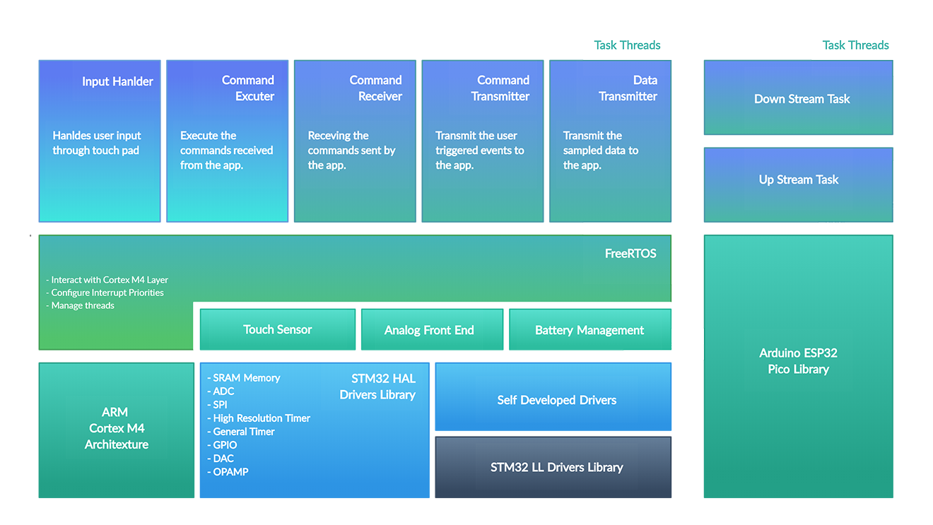
That separation left two critical problems to solve: sampling at a fixed interval and moving data without interrupting acquisition.
Deterministic Acquisition
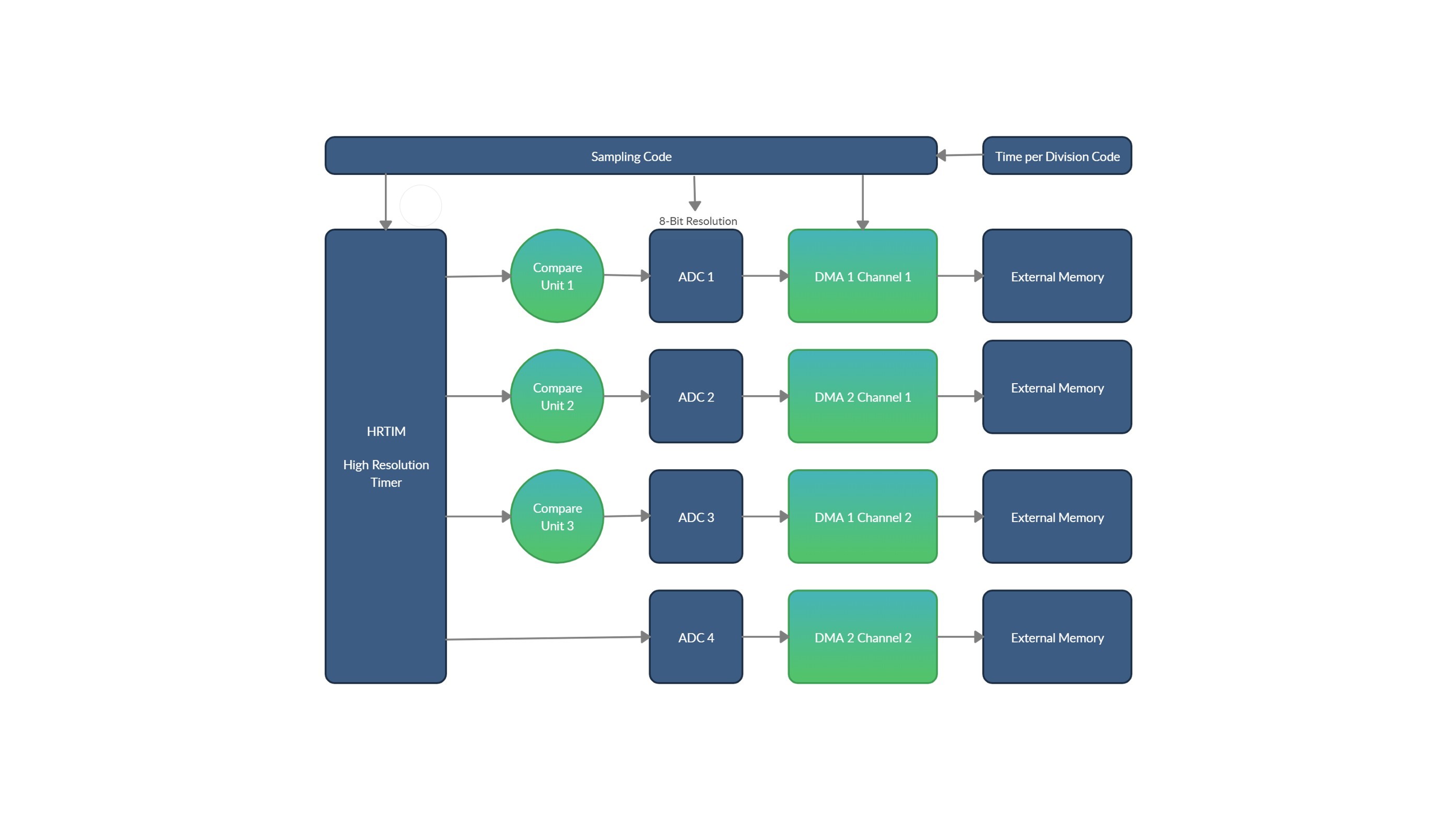
Fixed-interval sampling could not depend on software interrupt timing. The High Resolution Timer triggers the ADCs in hardware, and DMA moves each completed conversion directly into external SRAM.
Task Orchestration
The STM32 stack combines HAL drivers with targeted low-level drivers where tighter control was required. One example is repeated-start I2C communication with the touch sensor. FreeRTOS coordinates five tasks: three for communication and two for the instrument’s core logic. Semaphores protect the SPI bus and track empty and occupied queue slots.
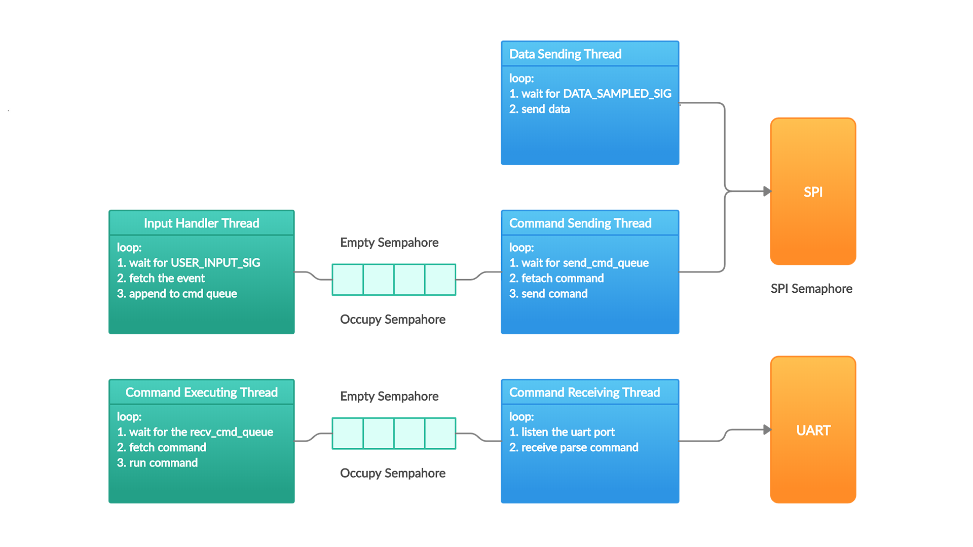
With acquisition and task coordination separated, the remaining problem is moving samples off the instrument without blocking either path.
Wireless Bridge
The ESP32 runs separate upstream and downstream paths. Sample data travels from the STM32 over SPI because throughput matters most in that direction. User commands return over UART, where the lower bandwidth is sufficient. The ESP32 then forwards both paths through UDP and TCP connections.
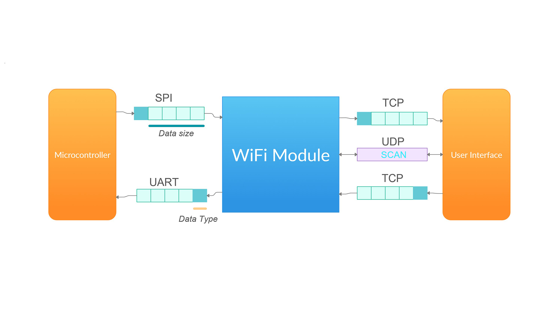
By the time samples reach the desktop, acquisition timing is already isolated from user interaction and network latency.
Software
Make the system feel like an instrument.
The desktop application follows a Model View Controller structure so acquisition, rendering, and interaction can evolve independently.
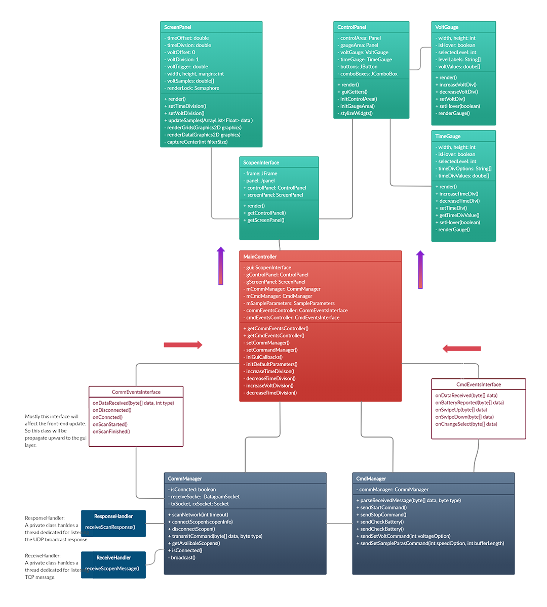
That separation keeps device communication out of the rendering path and gives the interface one consistent model of the current acquisition state.
Instrument Interface
We built the interface in Java Swing and drew the oscilloscope controls specifically for the product rather than relying on stock widgets. The result combines live signal display, acquisition controls, and device communication in one dark workspace.
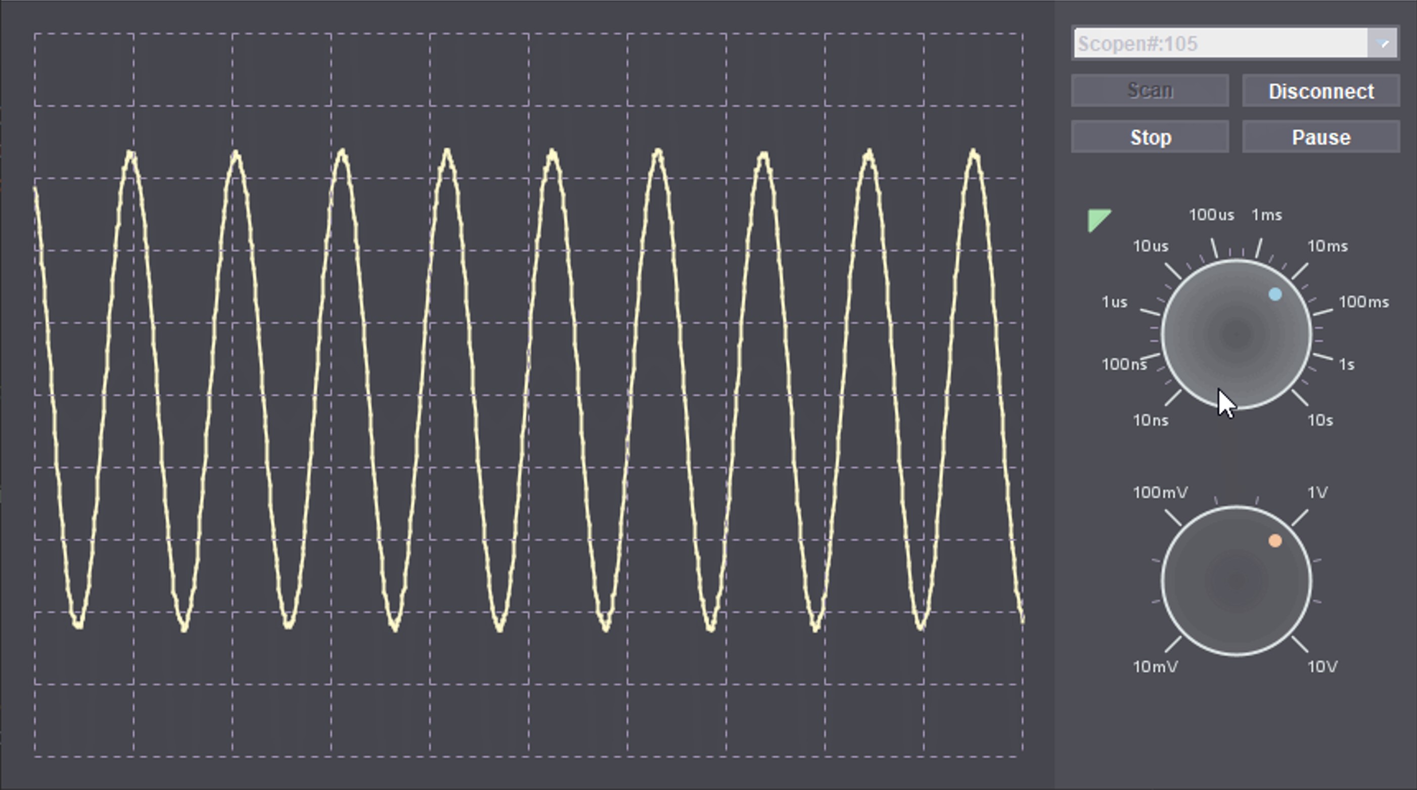
The interface completed the signal path, but the electronics still needed to become a device someone could hold.
Industrial Design
Turn the board into a handheld instrument.
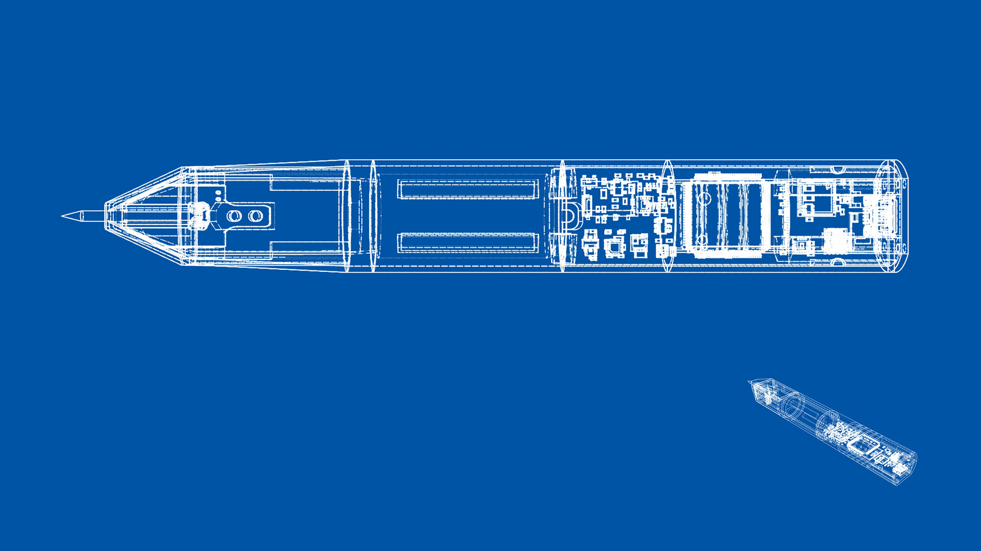
With the electrical and software systems working, the final task was packaging the board without compromising access to the probe, controls, or connectors.
We modeled the enclosure in Fusion 360, then printed and assembled several iterations at product scale.
Team
Scopen was created by three engineering students working across hardware, firmware, software, and industrial design.
Byron Aguilar
Electrical Engineer
-
 Boning DongComputer Engineer
-
 Cesar GonzalezElectrical Engineer
Acknowledgements
Thanks to Professor Yogananda Isukapalli for leading the UCSB Computer Engineering capstone program, Kyle Douglas and Aditya Wadaskar for their technical guidance, and Jeff Longo for his help with the mobile application.